Jet Airliners Still Navigate With 1920s Radio Tech
Long before GPS, and increasingly now wherever GPS is being jammed, aircraft find their way using radio beams from the ground. The first aircraft navigated by radio in 1920, and most of those beams still guide every flight today.
On this page
- VOR: VHF Omnidirectional Range
- NDB: Non-Directional Beacon
- Line of Sight? Sorry, flat-earthers.
- ILS: Instrument Landing System
- DME: Distance Measuring Equipment
- RNAV: Area Navigation (trigonometry)
- Theta-Theta (2x VOR)
- Rho-Theta (VOR & DME)
- Rho-Rho (2x DME)
- Radalt: Radar Altimeter
- TCAS: Traffic Collision Avoidance System
- SELCAL: Selective Calling
- Phased arrays
- Putting it all together
I’m a First Officer on the Airbus A350 – one of the most modern, advanced airliners in the world – and most people would be surprised to learn that GPS is just one of many tools we use to navigate. The very first aircraft found its way by radio back in 1920, and a century later we still lean on that same lineage of ground-based radio beams on every single flight.
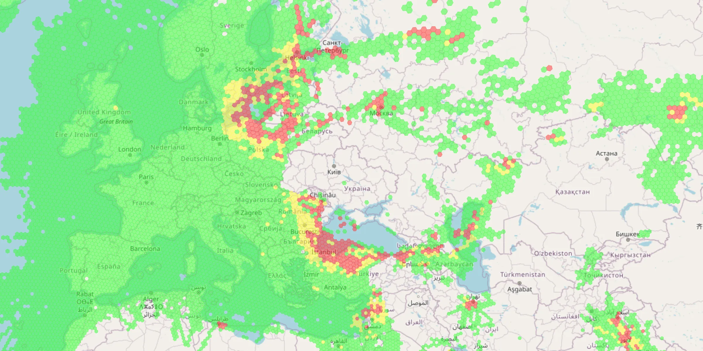
With the level of GPS jamming and spoofing in the world today, there are regularly long stretches of a flight where our satellite navigation is unusable, and the aircraft quietly falls back to its radio navaids to work out where it is.
Beyond just navigation, radio technology is used in a multitude of ways on a modern aircraft, and I think that many of them are interesting. When I learned about these technologies, it was from a textbook with static diagrams. Well, it’s 2026, and we can do a bit better with some interactive animations! Non-aviators will still be able to appreciate the elegance of these systems.
Going deep into each of these technologies could be a post all of its own, but without further ado, here are the ones that I will show you: VOR, DME, RNAV, ILS, radalt, TCAS, SELCAL, and phased arrays. The aviation industry does love a good acronym.
Bearing from a ground beacon. VHF, so line-of-sight only — but clean, with none of the NDB's static.
Tap a band to read what it does.
As a quick primer, we use different parts of the radio spectrum for different uses, all the way from LF up to SHF. Click on any of the bands to learn a little more about each one.
VOR: VHF Omnidirectional Range
Measure a precise bearing from a ground transmitter.
The VOR was developed in the late 1930s and 40s (the first station went live in 1946) and rolled out across the world through the 1950s. It’s still a staple of modern aviation radio navigation. It allows an aircraft to work out its precise bearing from the station, accurate to within about ± 1 degree. We call these bearings from the VOR station radials, so there are 360 whole-number radials for each VOR.

VORs are actually incredibly complex, with lots of signal analysis and math required to properly understand, but I will explain it at a high level.
The basic principle is that the VOR station transmits an omnidirectional (all direction) pulse signal periodically. A rotating direction signal sweeps around clockwise, and is at the magnetic north direction when the omnidirectional signal is transmitted.
A common analogy is to that of a lighthouse, with a single rotating light, and a light that flashes out a different colour in all directions when the rotating light points north.
By timing the difference between the peak of the omnidirectional signal and the sweeping signal, we can calculate which direction we are from the station. In real life, the signals both operate at 30Hz…a bit too quick to show in our animations.
One subtlety for radio geeks: the station pictured above is a Doppler VOR – that’s the ring of 48 antennas. In both types the reference is the fixed, omnidirectional signal and the variable is the direction-dependent one. What the Doppler design swaps is the modulation. A conventional VOR carries the reference as FM and generates the variable as AM by rotating an antenna pattern. The Doppler VOR flips that – the omnidirectional reference is now AM, and the variable is FM, synthesised by sweeping the transmission around the ring so that Doppler shift encodes the bearing (it even sweeps the opposite way, so an ordinary receiver still reads the right radial). The maths the aircraft decodes comes out identical, which is why DVOR and conventional VOR are interchangeable in the cockpit.
Note: this is not radar – the ground station does not know where the aircraft are located – the ground station is a blind transmitter.
In reality, the signal is not a single pulse, but is a wave.
Measuring the phase difference between the reference and variable signal will yield the magnetic bearing from the station.
The signal processing for this equipment is complex, but for pilots trying to make use of this information, we use an instrument in the flight deck called an HSI – Horizontal Situation Indicator.
I have slightly cheated here, and also included some RMI – Radio Magnetic Indicator – functionality in the form of the yellow arrow that points directly to the station.
This instrument combines one of the most important primary instruments – a compass – with information from the VOR.
The current heading of flight is always at the top. The yellow arrow always points towards the station (thus, the tail of the arrow indicates the radial of the station that we are currently on.)
There is a dial on the instrument called the OBS – Omni Bearing Selector – which allows us to select a radial to fly and track. With this selected, the magenta arrow will follow our selection.
The bar in the middle of the magenta arrow shows our deviation from the selected bearing. Each dot of the scale represents 5° of deviation (on this A350-style HSI there are two dots per side, so full-scale is 10°; the classic light-aircraft CDI instead packs five dots at 2° each). When using the instrument practically in flight, the bar being to the left indicates that we are right of track and need to fly-left. We will see this same pattern when we look at the ILS system.
Play with the sliders to see how they all interact with each other.
In addition to broadcasting navigation information, the omnidirectional signal also encodes an audio signal containing a Morse code identifier for the VOR. We want to know that we are using the correct signal!
VORs usually have a 3-letter identifier, usually named after their closest physical city or point of interest.
At London Heathrow, four VORs give their names to the famous holding stacks – the racetracks in the sky where inbound aircraft circle, sometimes for 20 minutes, waiting for their turn to land: OCK (Ockham), LAM (Lambourne), BNN (Bovingdon), BIG (Biggin Hill). If you’ve ever stared out of the window watching the same reservoir go past again and again on the way into Heathrow, you were orbiting one of these.
In light aircraft, you have to listen to the Morse to identify it manually, but most modern avionics do the decoding for us :)
A jet delivered in 2026 confirms it has tuned the right beacon by listening for Morse code – a scheme from the 1830s – being continuously beeped out by a station on the ground.
If you want to go deeper on VORs, this video is an interesting watch:
NDB: Non-Directional Beacon
A less precise, but longer-range precursor to VORs
Designed in the 1930s, the NDB is a more simplistic omnidirectional beacon that transmits in the LF/MF range. Its direction-finding ancestor, the low-frequency radio range, is the tech that first let airliners “fly the beam” across a continent in the 1920s and 30s – pilots literally listened for Morse tones in each ear and flew the course where they merged.
There is no directional information coded into the radio signal itself, but a directional radio antenna on the aircraft is able to sense the direction of the signal. Accuracy is usually in the ±5° range.
One advantage of the NDB frequency is that the radio waves follow the curvature of the earth, meaning that the signal can often be used beyond visual line-of-sight.
This type of signal is also prone to a series of errors such as night effect (skywave), coastal refraction, mountain effect – and thunderstorms: the needle will rotate to point at lightning when there is a nearby strike.
NDBs are slowly going extinct being decommissioned.
VORs, on the other hand, are not being allowed to die. Even as GPS took over, the FAA deliberately kept a backbone of them alive as the VOR Minimum Operational Network (MON): roughly 500 stations (down from around 950), spaced and boosted so that if GPS fails, any aircraft in the continental US is always within 100 nm of a VOR-and-ILS approach it can fly with no satellites at all.
Line of Sight? Sorry, flat-earthers.
Radio waves in the VHF spectrum travel in a straight line.
The earth is round (well, an oblate spheroid).
Problem spotted? VORs, which rely on a VHF signal transmitted from a little above ground level, thus have a pretty limited usefulness at the surface of the earth. Good thing we invented aircraft!
The rule of thumb used in the cockpit (which approximates more complicated math) is
radio horizon (in Nautical Miles)≈ 1.23 × √(height in feet)
ILS: Instrument Landing System
Follow a radio beam down to the runway, even in cloud.
With few exceptions, we almost always want to approach the runway in a straight line, at a 3° slope (we call it a glideslope – not a total misnomer since the power is often at idle and we are gliding all the way from cruise until the landing gear comes down – but I digress)
The system is split into two parts:
- Localizer for horizontal alignment
- Glideslope for vertical alignment
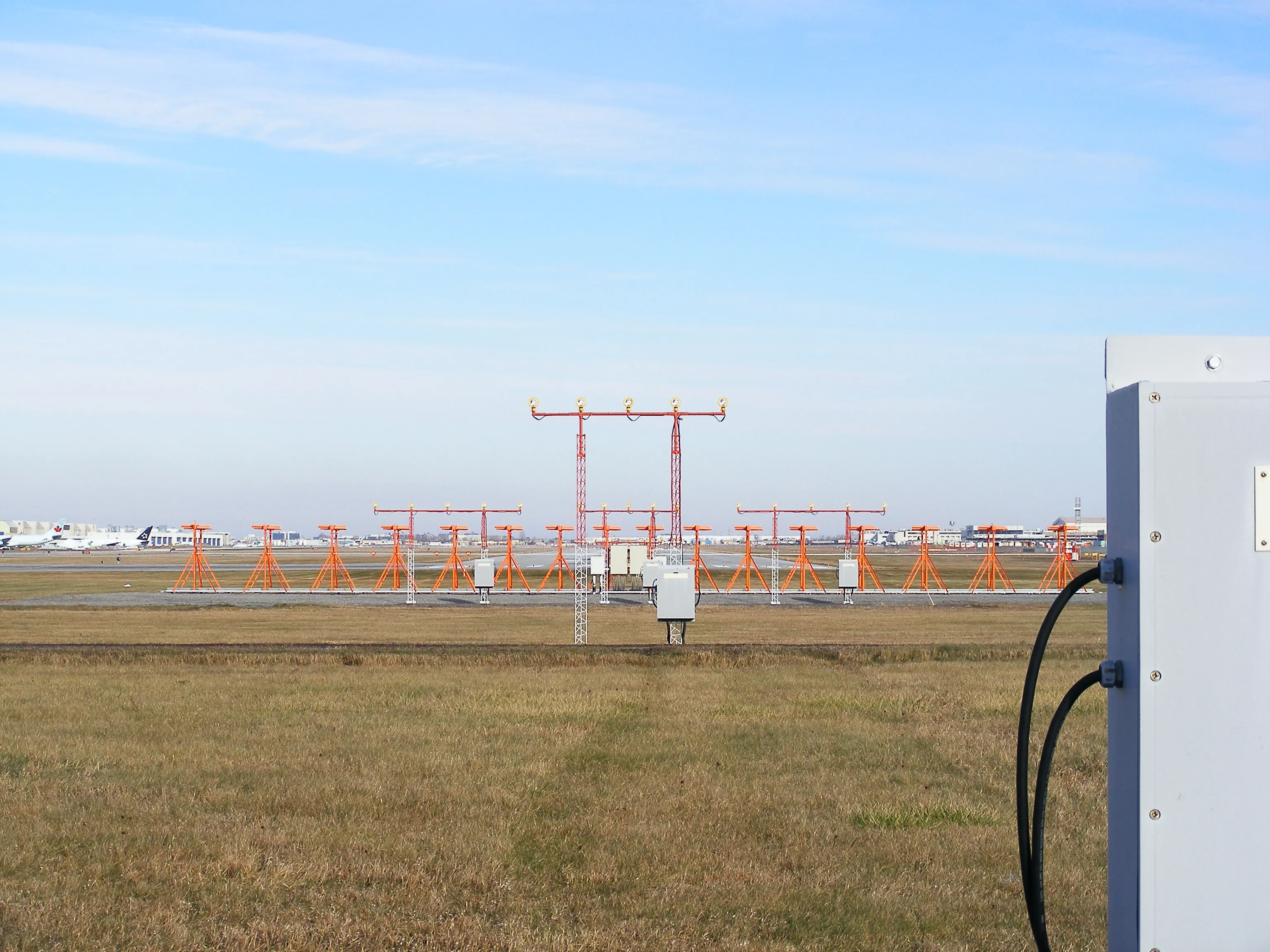
Both the localizer and glideslope work in the same manner: two amplitude-modulated signals are transmitted, one at 90Hz and the other 150Hz. Equipment in the aircraft measures the difference in signal strength (DDM – Difference in Depth of Modulation) of the two signals, and when they are of equal strength then we know we are on the correct path.
The “cone” look in the diagrams models real life. As you get closer to the runway, the system becomes far more sensitive.
Modern aircraft autopilots can automatically “lock on” to this signal to enable guidance down to very low levels – and even totally automatic landing if the ground equipment, aircraft, and pilots are all certified.
When flying manually, the magenta diamond is used in the same way as the deviation bar for the VOR. Diamond to the left = fly to the left.
DME: Distance Measuring Equipment
How far away is a ground station?
DME works by echo timing. The aircraft transmits a pair of pulses. When the ground station receives a pulse pair, it waits for exactly 50 µs before rebroadcasting the pulse pair in all directions.
Using the speed of light and subtracting the 50 µs fixed delay, we can calculate our distance to the station.
Note: it measures slant range: directly overhead at 36,000 ft the DME reads ~6 nm, not zero.
Usually a DME is paired with either a VOR or ILS, complementing the direction-finding ability of these systems.
An interesting side effect of being effectively a signal reflector is that there is no way to definitively discern our own replies from those of other aircraft. There is no specific coding in the pulses. A single DME can handle approximately 100 aircraft before it gets saturated.
To handle conflicting pulses, each aircraft deliberately jitters its interrogation timing at random, then keeps only replies at a constant lag after its own pulses.
Occasionally two interrogations land together and garble each other. In this case, the DME simply does not reply, and the aircraft will each make another attempt after a random delay.
Interestingly, this is essentially the same method that early Ethernet and Wi-Fi use to share a channel: detect the collision, then back off for a random interval before trying again.
RNAV: Area Navigation (trigonometry)
Fix your own position from one or more beacons.
If we know the precise coordinates of the ground stations for VORs or DMEs, then it follows that we can perform some high school trigonometry to identify our own position in space.
Theta-Theta (2x VOR)
With two VORs, we can calculate our location from the crossing point.
Because of the ±1° or so of inaccuracy inherent in the signal, the crossing angle of the two radials is important for a good position fix, with 90 degrees being optimal.
Rho-Theta (VOR & DME)
From a single VOR with co-located DME, we can accurately plot our position.
Rho-Rho (2x DME)
The most accurate of the three, this is the method that modern FMS systems use in combination with IRS and GPS to update and validate their location.
When only two DMEs are used, there is ambiguity due to the two crossing points. This is resolved using either a 3rd DME, or an existing location memory (from GPS or IRS).
Radalt: Radar Altimeter
How high above the ground are we?
This radar unit, installed in the belly of the aircraft, detects the nearest obstacle in an approximately 30° cone below the aircraft up to about 2500ft.
Because it is a true reflection of the ground profile, it is best suited for aircraft needs requiring accurate terrain clearance information (autoland, GPWS, automated callouts, etc).
The “Fifty, Forty, Thirty, Twenty, Ten” callouts are driven by this radar.
Fun fact: USA 5G phone towers operate in a nearby frequency band to the radalt system, which has necessitated filters to be installed on aircraft in order to use the system within the US.
TCAS: Traffic Collision Avoidance System
What aircraft are around us?
Aircraft equipped with TCAS constantly send out interrogations on 1030 MHz, asking for other aircraft in the vicinity to respond on 1090 MHz, independent of any ground ATC radar.
The transponder response contains the altitude of the aircraft, and a directional antenna on the aircraft allows the TCAS system to build a picture of proximate aircraft in 3 dimensions. The direction is determined by an array of 4 antennas that compares the phase of the 1090 MHz carrier signal.
Based on the closing velocity and geometry, the system provides a warning when traffic enters the TA (Traffic Advisory) envelope, and a warning with avoiding action when entering the RA (Resolution Advisory) envelope.
The transponders on the two aircraft coordinate over Mode S to ensure that resolutions (climb, descend, reversals) are correct for each aircraft and not in the same direction. Advisories are always vertical, and never involve a turn instruction.
Important note: the RA outranks any ATC direction. We always follow the RA generated by the TCAS system first, and advise ATC of our actions after.
SELCAL: Selective Calling
Touch tone telephone, over 1920s HF tech
We usually use VHF radio for communicating with ATC, but as you will remember from the VOR line-of-sight animation, the curvature of the earth means that these have a defined range limit.
For long range comms (over the middle of large oceans, usually), we communicate using HF radios, whose signals are capable of bouncing off the ionosphere to extend range far beyond the horizon.
The problem: HF radios produce a large amount of background static, and nobody wants to listen to static for hours across the Atlantic.
Enter SELCAL. Each aircraft is assigned a 4-letter code (registered to the aircraft, and rarely changed), which is our unique SELCAL code.
ATC can play this tone over the HF radio link, which will cause any aircraft with the matching code to play a ringing alert sound in the flight deck. This means we can take our headsets off and stop actively monitoring the radio, and wait for the very rare SELCAL if ATC need to get in touch with us.
Even in the era of satellite phones and CPDLC, we still use HF radio and SELCAL every time we cross the Atlantic.
Phased arrays
Steering a beam with nothing moving.
A bit more of a generic radio technology, but this one is used by our weather radar system.
Older weather radar systems contained a directional radar transmitter that physically swept left-to-right and tilted up and down to build a picture of the weather ahead.
A phased array steers its beam electronically – by shifting the phase of each element instead of physically pointing the antenna – so it can look in a new direction almost instantly, with no moving parts. Newer airborne radars lean heavily on this. My A350’s Honeywell IntuVue electronically scans multiple elevation slices to build a full 3D volume of the weather, rather than mechanically nodding a dish up and down.
It’s the same fundamental trick behind military AESA radars and the Starlink dish that steers at the sky with nothing visibly moving.
Putting it all together
Push back at Heathrow and the SID we fly (a pre-defined departure route) is an RNAV departure — GPS is doing the steering from the first turn. The system computing our position isn’t trusting GPS alone, it’s cross-checking against a variety of DME/DME fixes and the IRS, voting on whether the GPS answer looks sane.
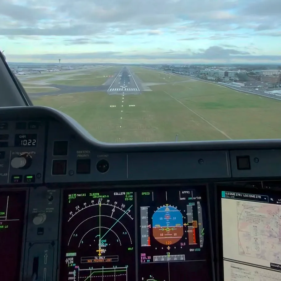
Over the Atlantic ocean we contact a radio station 1000+ miles away on HF and check with ATC that our SELCAL works so that we can be reached by the controller if needed — satellite comms and datalink haven’t displaced HF yet. Then GPS quietly drops out in a jammed patch of sky, and so the aircraft starts using IRS and DME/DME and keeps drawing an accurate line on the map. We approach the runway to land by locking on to the ILS, and the radalt counts down — “fifty, forty, thirty, twenty, ten” — all the way to the ground.
GPS does most of the steering, most of the time. But all of this older radio kit is still there underneath, still working away — the VOR, DME and ILS ready to take over the moment GPS drops out, and TCAS, the radalt, HF and SELCAL each quietly doing their own job.
It’s a whole century of radio engineering, and almost none of it has been thrown away. Also, it’s just kind of cool — especially with animations you can play with.
If you enjoyed this, you might also like the interactive graphs and charts behind my actual flying – routes, hours and aircraft – on my Pilot page.
Also important to note: I’m a line pilot rather than an avionics engineer, so if I’ve oversimplified something or you know a juicier detail, I’d genuinely love to hear it – corrections and questions welcome in the comments.